Antenna Design · Full-Wave Simulation
2.4 GHz Patch Antenna
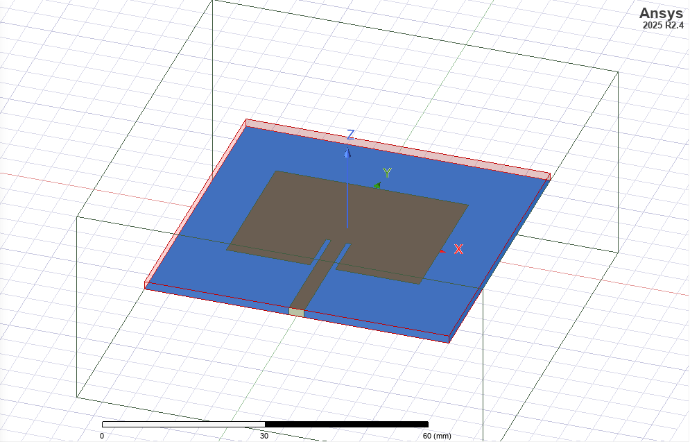
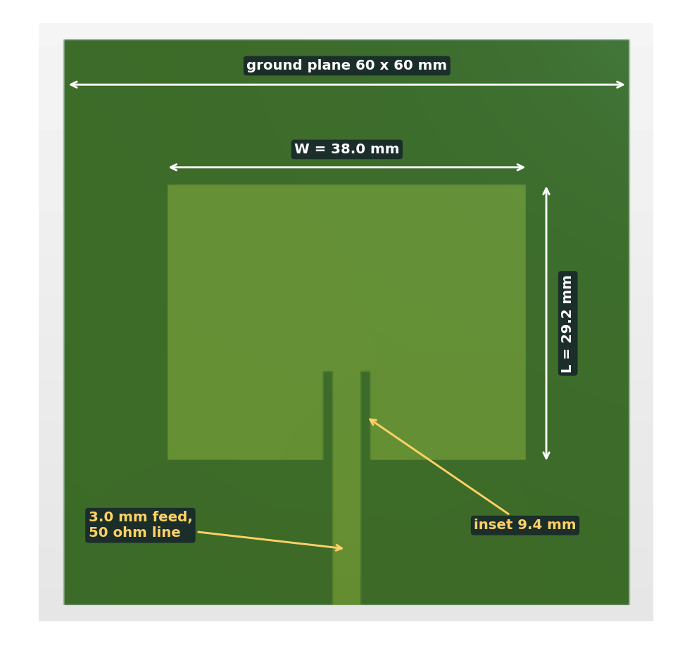
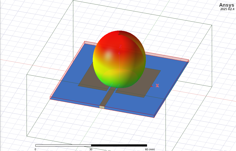
An inset-fed microstrip patch for the 2.4 GHz link, sized by hand from the transmission-line model and then handed to HFSS to check. The closed-form numbers and the full-wave solve landed within 0.02 mm of each other.
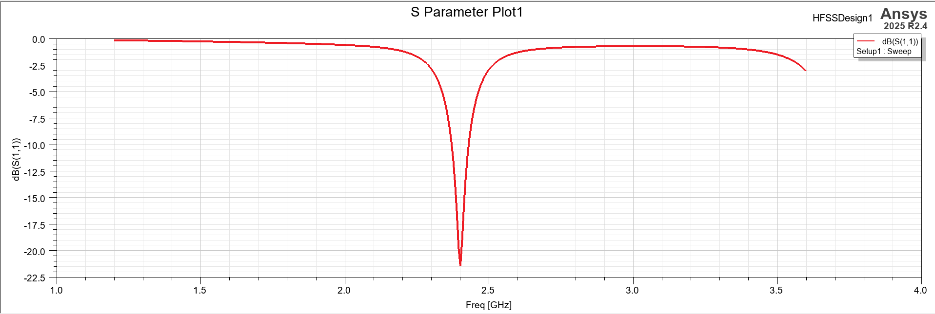
| Return loss at 2.4 GHz | -21.4 dB |
|---|---|
| Bandwidth | 66 MHz at -10 dB · 69 MHz under VSWR 2:1 |
| Peak directivity | 6.55 dBi, broadside |
| Front-to-back ratio | 14.5 dB on a 60 x 60 mm ground plane |
| Patch | 38.0 x 29.4 mm · 9.4 mm inset · 3 mm feed |
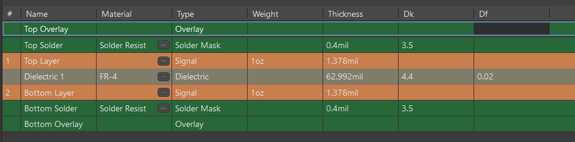
| Substrate | 1.6 mm FR-4, εr = 4.4, tanδ = 0.02 |